Interfacing Nokia 5110 LCD with MSP430
by Luan
Posted on 9 February 2017, 13:34
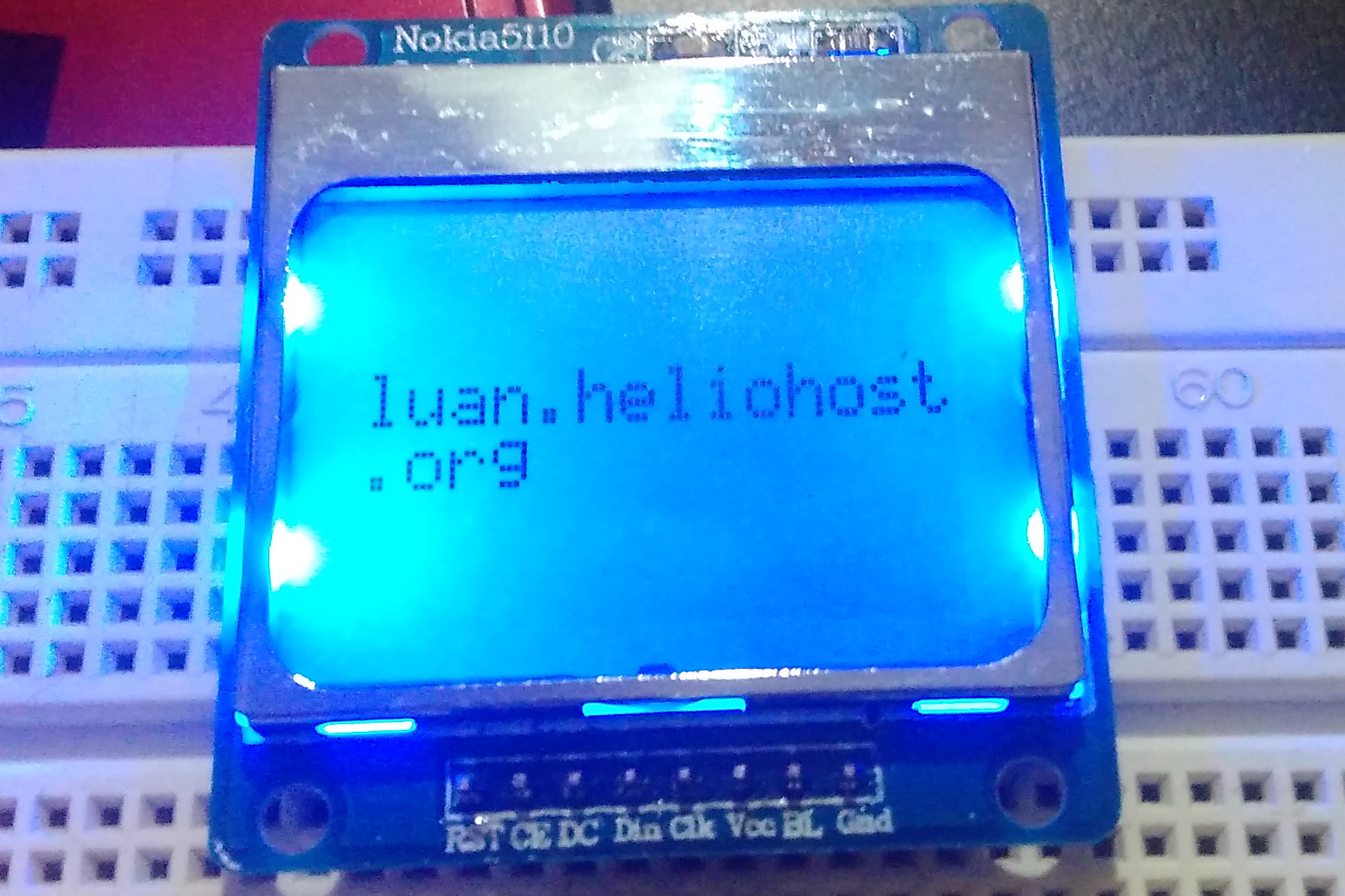
In this post I show how interface the Nokia 5110 lcd module. The Nokia 5110 is a basic graphic lcd screen for lots of applications, it uses the PCD8544 controller, designed to drive a graphic display of 48 rows and 84 columns.
As I said in previous post, I will show how interface the Nokia 5110 LCD with MSP430. The Nokia 5110 is a basic graphic LCD screen for lots of applications. It was originally intended for as a cell phone screen. This one is mounted on an easy to solder PCB.
It uses the PCD8544 controller, which is the same used in the Nokia 3310 LCD. The PCD8544 is a low power CMOS LCD controller/driver, designed to drive a graphic display of 48 rows and 84 columns. All necessary functions for the display are provided in a single chip, including on-chip generation of LCD supply and bias voltages, resulting in a minimum of external components and low power consumption. The PCD8544 interfaces to microcontrollers through a serial bus interface.
Connection with MSP430
The communication with LCD controller is made through a serial interface, it minimizes the number of IO pins needed.
RST	 -> P1.0
CE	 -> P1.1
DC	 -> P1.2
DIN	 -> P1.3
CLK	 -> P1.4
BL	 -> P1.5
VCC	 -> VCC
GND	 -> GND
Working principle
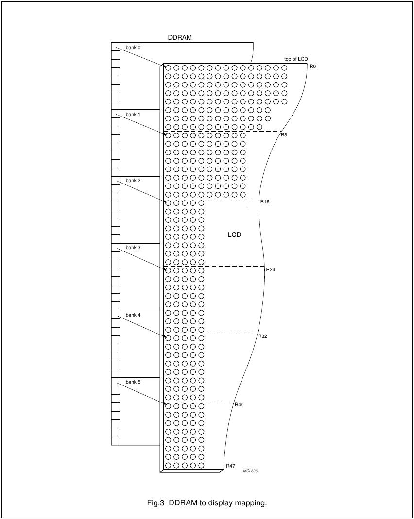
Like in the 16×2 LCD, in Nokia 5110 the displays shows the content of DDRAM. The RAM is divided into six banks of 84 bytes (6 × 8 × 84 bits). During RAM access, data is transferred to the RAM through the serial interface.
The process of data transferring can be done in rates of until 4Mbps. The process is simple, some approaches use the SPI interface to do this task but a full implementation is not difficult.
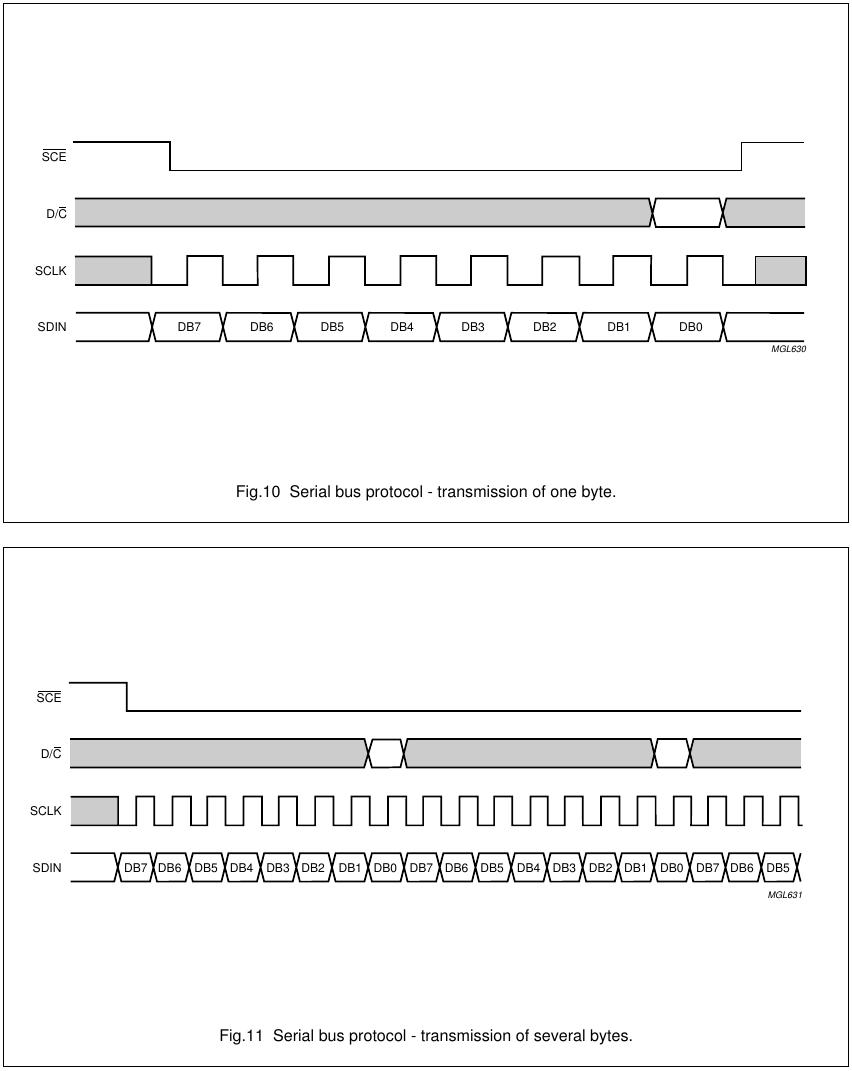
The instruction format is divided into two modes: If D/C (mode select) is set LOW, the current byte is interpreted as command byte, if it is set HIGH the current byte is interpreted as a command. The level of the D/C signal is read during the last bit of data byte.
Each instruction can be sent in any order to the PCD8544. The MSB of a byte is transmitted first. The serial interface is initialized when SCE is HIGH. In this state, SCLK clock pulses have no effect and no power is consumed by the serial interface. A negative edge on SCE enables the serial interface and indicates the start of a data transmission.
More details can be found on Datasheet of PCD8544
The source code
Different from the 16×2 LCD, it’s a graphical display and don’t have a internal font table. When used in text mode, you need to have your own font table and write characters Byte by Byte.
// LCD Nokia 5110 Interface
// Author: Luan Ferreira Reis de Jesus

#include <msp430g2553.h>
#include "font_table.h"

#define RST	BIT0
#define CE	BIT1
#define DC	BIT2
#define DIN	BIT3
#define CLK	BIT4
#define BL	BIT5


void delay_us(unsigned int us)
{
    while (us)
    {
        // 1 for 1 Mhz set 16 for 16 MHz
        __delay_cycles(1);
        us--;
    }
}


void delay_ms(unsigned int ms)
{
    while (ms)
    {
        // 1000 for 1MHz and 16000 for 16MHz
        __delay_cycles(1000);
        ms--;
    }
}


void configure_clocks()
{
    // Stop watchdog
    WDTCTL = WDTPW + WDTHOLD;
    BCSCTL1 = CALBC1_1MHZ;
    DCOCTL = CALDCO_1MHZ;
}


void send_byte(unsigned char byte)
{
    unsigned char i;
    for (i = 0; i < 8; i++)
    {
        P1OUT &= (0xFF & ~CLK);
        if (byte > 127) {
            P1OUT |= DIN;
        }
        else
        {
            P1OUT &= (0xFF & ~DIN);
        }

        delay_us(1);
        // rise clock
        P1OUT |= (CLK);

        // shift byte
        byte = byte << 1;
    }
    P1OUT &= (0xFF & ~CLK);
}


void send_data(unsigned char data)
{
    P1OUT |= DC;
    send_byte(data);
}


void send_command(unsigned char cmd)
{
    P1OUT &= (0xFF & ~DC);
    send_byte(cmd);
}


void init_lcd()
{
    P1DIR |= RST | CE | DC | DIN | CLK | BL;

    P1OUT = RST | CE | DC | ~DIN | ~CLK | ~BL;
    delay_ms(50);

    // reset the controller
    P1OUT &= (0xFF & ~RST);
    delay_us(1);
    P1OUT |= (RST);

    // start
    P1OUT &= (0xFF & ~CE);
    send_command(0x21);
    send_command(0x99);    // set LCD Vop (contrast)
    send_command(0x20);    // LCD basic commands
    send_command(0x0C);

    // turn on backlight
    P1OUT |= (BL);
}


void clear_display()
{
    unsigned short i;
    for(i = 0; i < 504; i++)
    {
        send_data(0x00);
    }
}


void set_cursor(unsigned char x, unsigned char y)
{
    unsigned char x_addr = 0x80 | x;
    unsigned char y_addr = 0x40 | y;
    send_command(0x20);
    send_command(x_addr);
    send_command(y_addr);
}


void print_char(char c)
{
    unsigned char i;
    for (i = 0; i < 5; i++)
    {
        send_data(font[c - 0x20][i]);
    }
    send_data(0x00);
}


void print_string(char *str)
{
    while(*str)
    {
        print_char(*str);
        str++;
    }
}


int main()
{
    //configure the clock frequency
    configure_clocks();

    // init lcd
    init_lcd();

    // clear the display
    clear_display();

    set_cursor(0, 2);
    print_string("luan.heliohost.org");

    P1OUT |= CE;
    while (1)
    {

    }
}
The full project can be downloaded in the GitHub.
Category MSP430
Comments
Enter your comment below. Fields marked * are required. You must preview your comment before submitting it.
Comments are turned off for this article.
akhtar 10 April 2017, 21:09
i run this code in ccs but it shows font is undefined error ,what is the solution for this
Luan 11 April 2017, 13:28
You need to download the file font_table.h from github too. And put in same folder.
akhtar 11 April 2017, 20:03
hello luan
error is solved, but still i cant get output ,what is issue ?i think itspinmuxing problem?what is the issue ?why the output will not come?
thanks and regards
akhtar
akhtar 11 April 2017, 23:13
and also u r not define any spi pin how data is write in to the lcd (how clock and data are sink)..i m not getting any output.// LCD Nokia 5110 Interface
#include <msp430.h>
#include “font_table.h”
#define RST BIT0
#define CE BIT1
#define DC BIT2
#define DIN BIT7
#define CLK BIT5
#define BL BIT3
void spi_init(void)
{ // set the pin mode 3 for pins 5,6 & 7 of port 1 (USCI mode)
P1SEL |= BIT5 + BIT7; // low bit = 1 for pins 5,6 and 7 BIT 3 is 0 (CS via GPIO)
P1SEL2 |= BIT5 + BIT7; // high bit = 1 for pins 5,6 and 7 BIT 3 is 0 (CS via GPIO)
//P1DIR |= BIT4; // p1.4 set to output to drive CS //P1OUT |= BIT4; // pull p1.4 to high – CS high -> chip is disabled
UCB0CTL1 = UCSWRST;
UCB0CTL0 |= UCCKPH | UCMST | UCSYNC | UCMSB | UCMODE_0; // synchronous (=SPI) master 3 wire SPI, clock polarity Low at idle // SPI mode 0
UCB0CTL1 |= UCSSEL_2; //use SCLK : 4MHz
UCB0BR0 = 0×04; // set baud rate = SMCLK, divide by 4, SPI Clock Freq : 1 MHz
UCB0BR1 = 0;
UCB0CTL1 &= ~UCSWRST; // ** Initialize USCI **
}
void delay_us(unsigned int us)
{
while (us)
{
// 1 for 1 Mhz set 16 for 16 MHz
__delay_cycles(1);
us—;
}
}
void delay_ms(unsigned int ms)
{
while (ms)
{
// 1000 for 1MHz and 16000 for 16MHz
__delay_cycles(1000);
ms—;
}
}
void configure_clocks()
{
// Stop watchdog
WDTCTL = WDTPW + WDTHOLD;
BCSCTL1 = CALBC1_1MHZ;
DCOCTL = CALDCO_1MHZ;
}
void send_byte(unsigned char byte)
{
unsigned char i;
for (i = 0; i < 8; i++)
{
P1OUT &= (0xFF & ~CLK);
if (byte > 127) {
P1OUT |= DIN;
}
else
{
P1OUT &= (0xFF & ~DIN);
}
void send_data(unsigned char data)
{
P1OUT |= DC;
send_byte(data);
}
void send_command(unsigned char cmd)
{
P1OUT &= (0xFF & ~DC);
send_byte(cmd);
}
void init_lcd()
{
//P1SEL |=BIT2;
//P1SEL2 |=BIT2;
P1DIR |= RST | CE | DC | DIN | CLK | BL;
void clear_display()
{
unsigned short i;
for(i = 0; i < 504; i++)
{
send_data(0×00);
}
}
void set_cursor(unsigned char x, unsigned char y)
{
unsigned char x_addr = 0×80 | x;
unsigned char y_addr = 0×40 | y;
send_command(0×20);
send_command(x_addr);
send_command(y_addr);
}
void print_char(char c)
{
unsigned char i;
for (i = 0; i < 5; i++)
{
send_data(font[c – 0×20][i]);
}
send_data(0×00);
}
void print_string(char *str)
{
while(*str)
{
print_char(*str);
str++;
}
}
void main(void)
{
//configure the clock frequency
configure_clocks(); spi_init();
// init lcd init_lcd(); // clear the display clear_display(); set_cursor(0, 2); print_string(“AKHTAR”); P1OUT |= CE; while (1) { } } just see my code still i m not getting any output ,whats the problemakhtar 12 April 2017, 01:09
i m using UCB0TXBUF in set_byte function ,still it will not working
send_byte()
{
UCB0TXBUF = byte;
while (!( IFG2 & UCB0TXIFG));
}
pankaj kyada 14 April 2017, 08:20
my code is not getting lcd output
#include <.h>
#include “font_lut.h”
#include “types.h”
#define RST BIT0
#define DC BIT1
#define BL BIT2
#define CE BIT3
#define DIN BIT7
#define CLK BIT5
void delay_us(unsigned int us)
{
while (us)
{
// 1 for 1 Mhz set 16 for 16 MHz
__delay_cycles(1);
us—;
}
}
void delay_ms(unsigned int ms)
{
while (ms)
{
// 1000 for 1MHz and 16000 for 16MHz
__delay_cycles(1000);
ms—;
}
}
void glcd_clk_init(void)
{
BCSCTL1 = CALBC1_1MHZ;
DCOCTL = CALDCO_1MHZ;
}
void glcd_write(u8 lcd_char)
{
P1OUT |= CE; // Enable Device..
P1OUT &= ~CE; // Disable Device…
//__delay_cycles(1000);
void glcd_cmd(u8 cmd)
{
P1OUT &= ~DC;
glcd_write(cmd);
}
void glcd_init(void)
{
P1DIR |= RST + DC + BL + CE;
P1OUT |= RST + DC + ~BL + CE;
void glcd_spi_init(void)
{
/* USCI SPI_B0 is used */
/* P1SEL = DIN | CLK;
P1SEL2 = DIN | CLK;*/
void glcd_char(char c)
{
unsigned char i;
void glcd_str(char *str)
{
while(*str)
{
glcd_char(*str);
str++;
}
}
void glcd_clr_disp(void)
{
unsigned short i;
for(i = 0; i < 504; i++)
{
P1OUT |= DC;
glcd_write(0×00);
}
}
void glcd_set_cursor(unsigned char x, unsigned char y)
{
unsigned char x_addr = 0×80 | x;
unsigned char y_addr = 0×40 | y;
glcd_cmd(0×20);
glcd_cmd(x_addr);
glcd_cmd(y_addr);
}
int main(void)
{
WDTCTL = WDTPW + WDTHOLD; // Stop watchdog
Luan 16 April 2017, 10:10
You may change the value in // set LCD Vop (contrast) command, instead 0×99 try use 0xE4
Search
About
I am computer engineer and MSc in Informatics graduated in Federal University of Espírito Santo. I am a programming and electronics enthusiast and I made this site to share my ideas and experiments in programming, electronics and DIY. I hope you enjoy it.
Donate: monero

452LPJcRqkhiaMdwpJSrzY1CTQ6MQMDxxQkUwDHDjBCe3Pcb6p9dHnGBZYjhZX1gHGU86W8wunHJBVDx5bk2K2aoFYwSA36