Using the 3.5 Inch (320x480) TFT LCD (ILI9488)
by Luan
Posted on 29 April 2017, 10:23
In this post I show how to interface with the TFT LCD driven by ILI9488 chip. I show how initialize it and send data to the screen. Using MSP430.
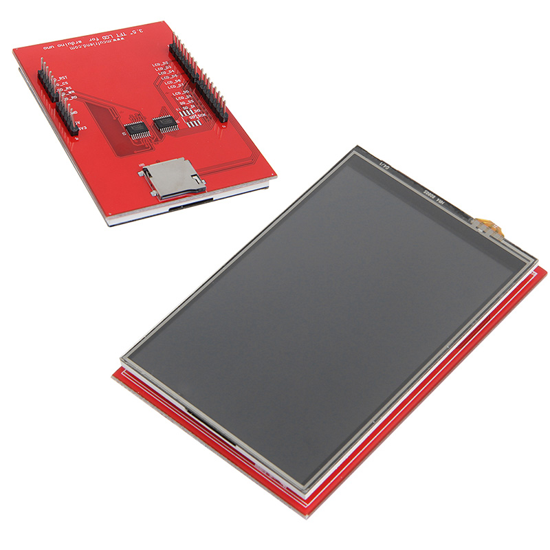
I am coming back to post after a while. Recently I acquired a graphic colored LCD TFT display. It is 3.5 inch have a resolution of 320×480 pixels and is controlled by ILI9488 driver. The module that I acquired is built as a shield for Arduino UNO, and a plus it also have touchscreen and a MicroSD interface.
In the first test I just made a simple interface between the LCD and the MSP430, and I implemented few functions to draw pixels, lines, circles and characters strings at the screen. This is just a simple example and can be improved. The code can be downloaded from github and was made to compile with MSPGCC.
Hardware connections
The communication with ILI9488 in this shield is made using a 8bit bus for data. Another 5 pins are used to control the data transfer as defined bellow.
#define LCD_RST	BIT0
#define LCD_CS	BIT1
#define LCD_RS	BIT2
#define LCD_WR	BIT3
#define LCD_RD	BIT4
The 8bit data are transferred by GPIO P1, and the P2 is used to hold the control pins.
Sending commands and data
The type of byte in the 8bit bus is divided in commands and data. When LCD_RS is low the sent byte is treated as a command by the ILI9488. When LCD_RS is high it is treated as data. The transferred byte is read by the driver during the rising edge of signal LCD_WR. The code snippet below shows the functions used for send commands and data.
// send command
void send_command(unsigned char cmd)
{
    P2OUT = 0x11;
    P1OUT = cmd;
    P2OUT |= (LCD_WR);
}

// send data
void send_data(unsigned char data)
{
    P2OUT = 0x15;
    P1OUT = data;
    P2OUT |= (LCD_WR);
}
Display initialization
Several commands need to be sent to display to initialize it properly. Basically it is used to reset the device, turn it on, set the display orientation (landscape or portrait), set the drawable region, cursor initial position, etc… The code utilized for initialization is shown below. The full commands explanation can be found on the ILI9488 Datasheet
// init lcd
void init_lcd()
{
    // reset LCD
    P2OUT &= (~LCD_RST);
    delay_ms(100);
    P2OUT |= (LCD_RST);

    // software reset
    send_command(0x01);
    delay_ms(100);

    // sleep out
    send_command(0x11);
    delay_ms(100);

    // memory acces control
    send_command(0x36);
    send_data(0xE8);
    delay_ms(100);

    // set dbi
    send_command(0x3A);
    send_data(0x06);
    delay_ms(100);

    // partial mode on
    send_command(0x12);
    delay_ms(100);

    // display on
    send_command(0x29);
    delay_ms(100);

    // set cursor
    send_command(0x2A);
    // set start x
    send_data(0x00);
    send_data(0x00);
    // set end x
    send_data(0x01);
    send_data(0xDF);
    send_command(0x00);

    send_command(0x2B);
    // set start y
    send_data(0x00);
    send_data(0x00);
    // set end y
    send_data(0x01);
    send_data(0x3F);
    send_command(0x00);

    delay_ms(100);

    // set brightness
    send_command(0x51);
    send_data(0x0F);
    delay_ms(100);

    // set brightness control
    send_command(0x53);
    send_data(0x2C);
    delay_ms(100);

    // set framerate
    send_command(0xB1);
    send_data(0xB0);
    send_data(0x11);
    delay_ms(50);

    set_bgcolor(0, 0, 0);

    P2OUT |= (LCD_CS);
    delay_ms(100);

}
Writting data to screen
After the initialization procedure, finally we can write data to screen. To write in the screen the command number is 0×2C, any data sent after this command will be write in the display, at the predetermined cursor position. The basic procedure to write the pixel in a given position with a given color is shown bellow.
// write pixel at position
void write_pixel(unsigned short x, unsigned short y, unsigned char r, unsigned char g, unsigned char b)
{
    set_address(x, y);
    P2OUT &= (~LCD_CS);
    send_command(0x2C);
    send_data(r);
    send_data(g);
    send_data(b);
}
The image bellow shows a example of what the defined functions can show at screen
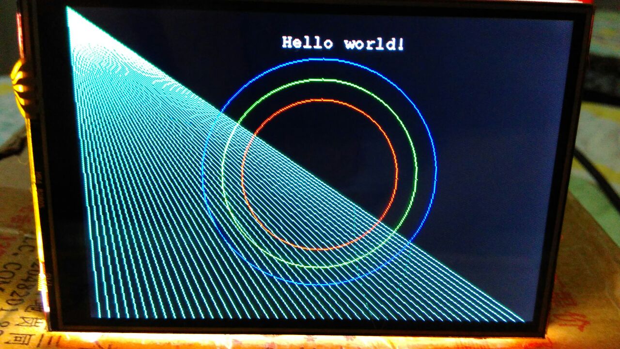
The complete code can be found in the github as I said in the beginning of post. I hope it may be useful, in next post I will use the same display with Arduino using the libraries that already are done and then I will can test the SD card interface and the touchscreen capabilities.
Category MSP430
Comments
Enter your comment below. Fields marked * are required. You must preview your comment before submitting it.
Bachurelis 12 December 2018, 12:10
Hello Luan,
Thank you for your post. Have you found the way to control back light?
I did not :(
Thanks.
Search
About
I am computer engineer and MSc in Informatics graduated in Federal University of Espírito Santo. I am a programming and electronics enthusiast and I made this site to share my ideas and experiments in programming, electronics and DIY. I hope you enjoy it.
Donate: monero

452LPJcRqkhiaMdwpJSrzY1CTQ6MQMDxxQkUwDHDjBCe3Pcb6p9dHnGBZYjhZX1gHGU86W8wunHJBVDx5bk2K2aoFYwSA36