Interfacing 16x2 LCD with MSP430
by Luan
Posted on 31 January 2017, 13:57
In this post will you find some basic tests with 16×2 lcd display using the MSP430 Launchpad.
In this post will you find some basic tests with 16×2 LCD display using the MSP430. It is a widely used display controlled by the Hitachi HD44780. This display is able to show 2 lines of 16 alphanumeric characters.
Character LCDs use a 16 contact interface, commonly using pins or card edge connections on 0.1 inch (2.54 mm) centers. Those without backlights may have only 14 pins, omitting the two pins powering the light. The pinout is as follows:
- Ground
- VCC (+3.3 to +5V)
- Contrast adjustment (VO)
- Register Select (RS). RS=0: Command, RS=1: Data
- Read/Write (R/W). R/W=0: Write, R/W=1: Read (This pin is optional due to the fact that most of the time you will only want to write to it and not read. Therefore, in general use, this pin will be permanently connected directly to ground.)
- Clock (Enable). Falling edge triggered
- Bit 0 (Not used in 4-bit operation)
- Bit 1 (Not used in 4-bit operation)
- Bit 2 (Not used in 4-bit operation)
- Bit 3 (Not used in 4-bit operation)
- Bit 4
- Bit 5
- Bit 6
- Bit 7
- Backlight Anode (+) (If applicable)
- Backlight Cathode (-) (If applicable)
Connection with MSP430
The hardware assembly of this project is very simple. The commication with display is done using 8-bits or 4-bits, to save I/O pins is commonly used the 4-bit operation mode. In this case the data is send in two parts: first the upper nibble is sent and after the lower nibble is sent. The connection between LCD and MSP430 is as follow:
- GND;
- +5V;
- This pin is connected to a trimpot to adjust the display contrast;
- RS <—— Connected to P1.0
- R/W <—— Connected to P1.1
- Enable <—— Connected to P1.2
- NC
- NC
- NC
- NC
- Bit 4 <—— Connected to P1.4
- Bit 5 <—— Connected to P1.5
- Bit 6 <—— Connected to P1.6
- Bit 7 <—— Connected to P1.7
- +3.3 V
- GND
Display initialization
Communicating with LCD controller requires to follow a specific initialization sequence. The commands and timings must be respected in order to achieve a proper work in desired mode. The following diagram shows the initialization sequence for the JHD162A (The device that I utilized, some variations in timings can happens depending on lcd display manufacturer).

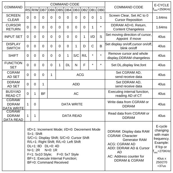
The full instruction set of the controller is showed in next table:
Writting data
The display shows data in DDRAM, the DDRAM address corresponds to cursor position.
Font table
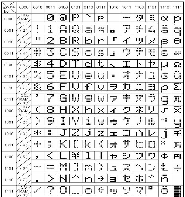
The HD44780 come with a font table stored in the ROM, this table contains the ASCII characters and some extra characters depending on the version of controller. The default table for the HD44780UA00 (Japanese Version):
Source code
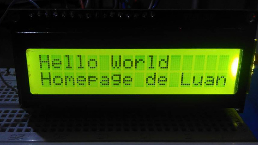
The code that implements a simple program is showed below. It just implements the initialization routine and prints a “Hello world”.
// interfacing 16x2 LCD
// Author: Luan Ferreira Reis de Jesus

#include <msp430g2553.h>

// define RS high
#define DR P1OUT = P1OUT | BIT0

// define RS low
#define CR P1OUT = P1OUT & (~BIT0)

// define Read signal R/W = 1 for reading
#define READ P1OUT = P1OUT | BIT1

// define Write signal R/W = 0 for writing
#define WRITE P1OUT = P1OUT & (~BIT1)

// define Enable high signal
#define ENABLE_HIGH P1OUT = P1OUT | BIT2

// define Enable Low signal
#define ENABLE_LOW P1OUT = P1OUT & (~BIT2)

void configure_clocks()
{
  // Stop watchdog
  WDTCTL = WDTPW + WDTHOLD;
  BCSCTL1 = CALBC1_1MHZ;
  DCOCTL = CALDCO_1MHZ;
}


void delay_us(unsigned int us)
{
  while (us)
  {
    // 1 for 1 Mhz set 16 for 16 MHz
    __delay_cycles(1);
    us--;
  }
}


void delay_ms(unsigned int ms)
{
  while (ms)
  {
    // 1000 for 1MHz and 16000 for 16MHz
    __delay_cycles(1000);
    ms--;
  }
}


void data_write(void)
{
  ENABLE_HIGH;
  delay_ms(5);
  ENABLE_LOW;
}


void send_data(unsigned char data)
{
  unsigned char higher_nibble = 0xF0 & (data);
  unsigned char lower_nibble = 0xF0 & (data << 4);

  delay_us(200);

  WRITE;
  DR;
  // send higher nibble
  P1OUT = (P1OUT & 0x0F) | (higher_nibble);
  data_write();

  // send lower nibble
  P1OUT = (P1OUT & 0x0F) | (lower_nibble);
  data_write();
}


void send_string(char *s)
{
  while(*s)
  {
    send_data(*s);
    s++;
  }
}


void send_command(unsigned char cmd)
{
  unsigned char higher_nibble = 0xF0 & (cmd);
  unsigned char lower_nibble = 0xF0 & (cmd << 4);

  WRITE;
  CR;
  // send higher nibble
  P1OUT = (P1OUT & 0x0F) | (higher_nibble);
  data_write();

  // send lower nibble
  P1OUT = (P1OUT & 0x0F) | (lower_nibble);
  data_write();
}


void lcd_init(void)
{
  P1DIR |= 0xFF;
  P1OUT &= 0x00;

  delay_ms(15);
  send_command(0x33);

  delay_us(200);
  send_command(0x32);

  delay_us(40);
  send_command(0x28); // 4 bit mode

  delay_us(40);
  send_command(0x0E); // clear the screen

  delay_us(40);
  send_command(0x01); // display on cursor on

  delay_us(40);
  send_command(0x06); // increment cursor

  delay_us(40);
  send_command(0x80); // row 1 column 1
}


int main(void)
{
  configure_clocks();

  lcd_init();

  send_string("Hello world!");
  send_command(0xC0);
  send_string("Homepage de Luan");

  while (1)
  {
  }
}
The full project can be downloaded in the GitHub. At this step you might set the development environment like shown in previous article. More things can be done to improve this code, specially removing the delays. As the LCD is a ‘slow device’, the microcontroller usually hangs much on delays during commands, this time could be used to make other tasks.
I hope that post might be useful, in next post I hope to show how to interface with the graphical display Nokia 5110. See you there
Category MSP430
Comments
Enter your comment below. Fields marked * are required. You must preview your comment before submitting it.
Search
About
I am computer engineer and MSc in Informatics graduated in Federal University of Espírito Santo. I am a programming and electronics enthusiast and I made this site to share my ideas and experiments in programming, electronics and DIY. I hope you enjoy it.
Donate: monero

452LPJcRqkhiaMdwpJSrzY1CTQ6MQMDxxQkUwDHDjBCe3Pcb6p9dHnGBZYjhZX1gHGU86W8wunHJBVDx5bk2K2aoFYwSA36